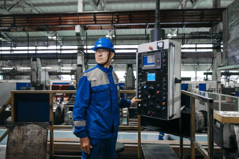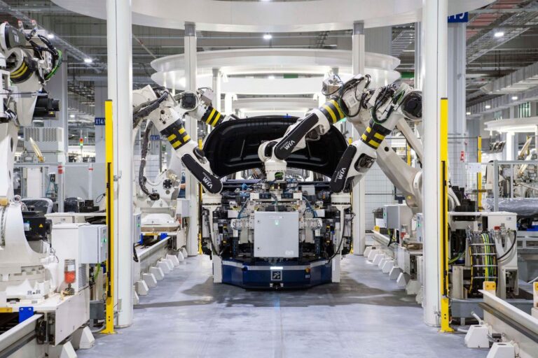
The modern manufacturing floor is a complex ecosystem of interdependent variables. When a machine fails, a batch is scrapped, or a safety incident occurs, the immediate symptom is obvious. The underlying cause, however, is rarely visible on the surface. Manufacturers who rely on guesswork or intuition to solve these problems often find themselves trapped in a cycle of recurring failures, treating symptoms while the root cause remains hidden.
To break this cycle, organizations must adopt structured problem-solving methodologies that force cross-functional teams to systematically map every potential contributing factor. The fishbone diagram is the foundational tool for this process. By visually organizing causes into distinct categories, this method prevents teams from jumping to conclusions and ensures that no variable (whether human, mechanical, or environmental) is overlooked.
This comprehensive guide explores the mechanics of the fishbone diagram, its application in manufacturing root cause analysis, and how connected factory technologies are transforming this static tool into a dynamic engine for continuous improvement.
What Is a Fishbone Diagram?
A fishbone diagram is a visual root cause analysis tool that helps manufacturers reduce recurring defects by up to 30% by systematically identifying, categorizing, and displaying all potential causes of a specific problem or effect. The diagram derives its name from its structure, which resembles the skeleton of a fish. The “head” of the fish represents the problem statement, while the “bones” branching off the central spine represent the major categories of potential causes.
Developed in the 1960s by Kaoru Ishikawa, a Japanese quality control expert and professor at the University of Tokyo, the tool was originally designed to help workers at the Kawasaki shipyards understand how various factors contributed to complex manufacturing defects. Today, the Ishikawa diagram is recognized globally as one of the Seven Basic Tools of Quality, alongside the Pareto chart, control chart, histogram, check sheet, scatter diagram, and stratification.
The primary function of a fishbone diagram is to facilitate structured brainstorming. When a cross-functional team encounters a stubborn production issue, the diagram provides a framework that forces participants to look beyond the most obvious culprits. By mapping out every conceivable variable, the team systematically tests and eliminates hypotheses until the true root cause is isolated.
What Are Cause-and-Effect Diagrams Also Known As?
Cause-and-effect diagrams are also known as Ishikawa diagrams or fishbone diagrams, and understanding these aliases ensures cross-functional teams communicate effectively during root cause analysis. The fishbone diagram is known by several aliases across different industries and disciplines. The most formal designation is the Ishikawa diagram, honoring its creator. In quality management literature, it is frequently referred to as a cause-and-effect diagram, which accurately describes its function of linking a specific outcome (the effect) to its contributing factors (the causes).
Another common alias is the herringbone diagram, a nod to the specific type of fish skeleton it resembles. In the healthcare sector, the term “fishbone” is also used in a completely different context: fishbone lab values. Medical professionals use a shorthand fishbone drawing (a skeletal diagram of intersecting lines) to quickly record and communicate Complete Blood Count (CBC) and Basic Metabolic Panel (BMP) lab results. While a blank lab fishbone diagram shares the skeletal visual metaphor, it is a data-recording shorthand, not a root cause analysis tool.
What Is the Anatomy of a Fishbone Drawing?
The anatomy of a fishbone drawing provides a structured framework that accelerates problem-solving sessions by organizing complex variables into clear visual categories. The effectiveness of a fishbone chart (or fish bone chart) lies in its simple, intuitive visual structure. A standard fishbone drawing consists of three primary anatomical components that work together to organize complex information.
The head of the fish, positioned on the far right of the diagram, contains the problem statement or the effect being analyzed. This statement must be specific, measurable, and clearly defined. A horizontal line, known as the spine, extends from the head to the left, serving as the central axis of the diagram.
The bones (or ribs) branch off the spine at an angle. These major branches represent the primary categories of potential causes. In manufacturing, these categories are typically defined by the 5Ms or 6Ms framework. Extending from these major bones are smaller sub-bones, which represent specific, granular causes within that category. For example, if a major bone is “Machine,” a sub-bone is “Worn cutting tool,” and a further sub-branch off that is “Preventive maintenance schedule ignored.”
What Are the 5Ms and 6Ms of Manufacturing?
The 5Ms and 6Ms of manufacturing provide a standardized categorization system that ensures cross-functional teams evaluate 100% of potential operational variables during a root cause analysis. To ensure a comprehensive fishbone analysis, the major bones of the fishbone diagram must cover all fundamental aspects of the production environment. The Toyota Production System established the 5Ms as the foundational framework for categorizing manufacturing variables. Over time, this evolved into the 6Ms to account for environmental factors.
| Entity | Attribute | Value |
|---|---|---|
| Manpower (People) | Definition | The human element involved in the process, including operators, maintenance technicians, and management. |
| Potential Causes | Lack of training, fatigue, miscommunication, low morale, or failure to follow standard operating procedures (SOPs). | |
| Machine (Equipment) | Definition | The physical assets, tools, and technology used to execute the manufacturing process. |
| Potential Causes | Tool wear, calibration drift, software glitches, lack of preventive maintenance, or outdated equipment. | |
| Material | Definition | The raw inputs, consumables, and components required to produce the final product. |
| Potential Causes | Supplier variability, degraded raw materials, incorrect specifications, or improper storage conditions. | |
| Method (Process) | Definition | The established procedures, workflows, and rules governing how the work is performed. |
| Potential Causes | Ambiguous work instructions, inefficient routing, outdated SOPs, or lack of standardized work. | |
| Measurement | Definition | The metrics, sensors, and inspection techniques used to evaluate the process and the product. |
| Potential Causes | Faulty gauges, incorrect tolerance limits, sampling errors, or misaligned key performance indicators (KPIs). | |
| Mother Nature (Environment) | Definition | The physical conditions of the facility and the external factors impacting the production floor. |
| Potential Causes | Temperature fluctuations, excessive humidity, poor lighting, vibration, or airborne contaminants. |
While the 6Ms framework is the standard for manufacturing, other industries use adapted categories. The service sector often uses the 4Ss (Surroundings, Suppliers, Systems, Skills), while marketing and administration use the 8Ps (Product, Price, Place, Promotion, People, Process, Physical Evidence, Performance).
How Do You Build a Fishbone RCA Template in 5 Steps?
Building a standardized fishbone RCA template in 5 steps reduces troubleshooting time by up to 40% by providing teams with a repeatable, structured problem-solving workflow. Creating an effective fishbone diagram root cause analysis requires more than just drawing lines on a whiteboard. It demands a structured, collaborative approach to ensure the resulting analysis is accurate and actionable. A standard fishbone RCA template follows a five-step process.
Step 1: Define the Problem Statement The foundation of any root cause analysis fishbone is a precise problem statement. Vague statements like “high scrap” or “machine broken” lead to unfocused brainstorming. The problem statement must be quantified using SMART criteria (Specific, Measurable, Achievable, Relevant, Time-bound). A strong problem statement reads: “CNC Lathe #4 experienced a 12% scrap rate due to dimensional variance during the Q3 production run.” This statement is placed in the head of the fish.
Step 2: Establish the Cause Categories Draw the spine extending from the problem statement and add the major bones. For a manufacturing issue, label these bones with the 6Ms (Manpower, Machine, Material, Method, Measurement, Mother Nature). This establishes the framework that will guide the brainstorming session and ensure no operational area is ignored. This forms the basis of your fishbone diagram template.
Step 3: Brainstorm Potential Causes Assemble a cross-functional team that includes operators, engineers, quality inspectors, and maintenance personnel. Encourage the team to brainstorm all possible factors that contribute to the problem statement. Place these factors on the diagram as sub-bones under the appropriate 6M category. The goal at this stage is volume; no idea is immediately discarded.
Step 4: Drill Down with the 5 Whys Once the initial causes are mapped, the team must drill deeper to differentiate between symptoms and root causes. Apply the “5 Whys” technique to the most likely sub-bones. If a cause is “Operator entered wrong parameter,” ask why. (Because the SOP was outdated). Ask why again. (Because document control failed to distribute the revision). This iterative questioning creates the smaller, tertiary branches on the Ishikawa diagram template.
Step 5: Prioritize and Test Hypotheses A completed rca fishbone template presents a landscape of hypotheses, not a definitive answer. The team must now prioritize the most probable root causes based on data, experience, and logical deduction. These prioritized causes are then tested on the shop floor. If testing confirms a root cause, the team develops a Corrective and Preventive Action (CAPA) plan to eliminate the issue permanently.
What Are Fishbone Diagram Examples in Manufacturing?
Reviewing specific fishbone diagram examples in manufacturing demonstrates how automotive, pharmaceutical, and electronics facilities use this tool to eliminate critical production bottlenecks. To understand how this methodology functions in practice, consider how different manufacturing sectors apply fishbone diagrams to solve specific production challenges. Here are three detailed fishbone diagram examples.
Example 1: Reducing Unplanned Downtime in Automotive Assembly: An automotive parts manufacturer experiences a sudden spike in unplanned downtime on a critical robotic welding cell. The problem statement is defined as: “Welding Cell B averaged 4.5 hours of unplanned downtime per week in October due to recurring fault codes.” During the fishbone analysis, the team maps causes across the 6Ms. Under “Machine,” they identify worn servo motors. Under “Method,” they note that the preventive maintenance schedule was extended from 30 to 45 days to meet production quotas. Under “Manpower,” they discover that new operators were not trained on the specific fault reset procedure. By visualizing these interconnected factors, the team realizes the root cause is a systemic failure to balance production demands with maintenance requirements, leading to accelerated wear and operator confusion. This is a classic fishbone diagram example manufacturing teams encounter daily.
Example 2: Eliminating Quality Escapes in Pharmaceutical Packaging: A pharmaceutical company detects a quality escape where blister packs are sealing with micro-leaks, compromising product sterility. The problem statement is: “Lot #8842 experienced a 3% micro-leak failure rate during secondary packaging.” The cross-functional team builds a fishbone diagram. Under “Material,” they investigate the foil backing supplier but find no variance. Under “Mother Nature,” they note a recent drop in facility humidity. Under “Machine,” they identify inconsistent pressure from the heated sealing roller. The 5 Whys analysis reveals that the sealing roller’s pneumatic cylinder is failing to maintain pressure because the ambient humidity drop caused the facility’s compressed air system to deliver dry, unlubricated air to the cylinder seals. The root cause spans environment, equipment, and facility infrastructure.
Example 3: Addressing High Scrap Rates in Electronics Manufacturing: A semiconductor facility struggles with a high scrap rate during the wave soldering process. The problem statement is: “Wave solder line 2 generated a 9% scrap rate due to solder bridging in Q1.” The fishbone analysis reveals multiple contributing factors. Under “Method,” the conveyor speed is found to be inconsistent. Under “Material,” the flux specific gravity is fluctuating. Under “Measurement,” the thermal profiling equipment is out of calibration. The team prioritizes the thermal profiling equipment. Testing confirms that because the measurement tool was uncalibrated, operators were unknowingly adjusting the pre-heat temperatures based on false data, causing the flux to activate improperly and resulting in solder bridges.
How Does Fishbone Analysis Integrate with Other Lean Tools?
Integrating fishbone analysis with other Lean tools like the 5 Whys and Pareto charts creates a comprehensive problem-solving ecosystem that permanently eliminates root causes. The fishbone diagram is rarely used in isolation. In mature Lean Six Sigma environments, it serves as the central hub that connects various analytical tools into a cohesive problem-solving workflow.
The most critical integration is with the 5 Whys methodology. While the fishbone diagram provides the horizontal breadth of the analysis (ensuring all categories are considered), the 5 Whys provides the vertical depth. Every sub-bone on the Ishikawa fishbone diagram should ideally be the result of a 5 Whys questioning sequence, ensuring the team has drilled past surface-level symptoms down to the fundamental systemic failure.
The fishbone diagram also pairs effectively with Pareto analysis. When a facility faces multiple interconnected problems, a Pareto chart (based on the 80/20 rule) is used first to identify the “vital few” defects causing the most significant financial or operational impact. Once the Pareto chart identifies the primary defect, that specific defect becomes the problem statement at the head of the fishbone diagram.
For highly complex or safety-critical systems, the fishbone diagram serves as a precursor to Failure Mode and Effects Analysis (FMEA). The brainstorming generated by the fishbone diagram helps populate the potential failure modes and causes required for a comprehensive FMEA matrix.
Finally, advanced practitioners sometimes utilize a reverse fishbone diagram. Instead of placing a problem at the head of the fish, the team places a desired goal or future state (e.g., “Zero Defects in Assembly”). The bones then represent the categories of actions, resources, and systemic changes required to achieve that goal, transforming the tool from a reactive troubleshooting method into a proactive strategic planning framework.
What Are the Limitations of a Static Fishbone Diagram?
The primary limitation of a static fishbone diagram is its reliance on subjective human memory, which often leads to biased analyses and delayed problem resolution. Despite its enduring popularity, the traditional whiteboard-and-sticky-note fishbone diagram has significant limitations in the context of modern, high-speed manufacturing. If the cross-functional team lacks a specific piece of historical context, that potential cause will simply not appear on the diagram. This subjectivity leads to biased analyses where teams focus on familiar problems rather than data-driven realities.
Furthermore, a static diagram is disconnected from the reality of the shop floor. When a team hypothesizes that “temperature fluctuation” is a root cause, they must leave the meeting room, manually pull historical HVAC logs, correlate them with production timestamps, and attempt to prove the hypothesis. This manual data gathering is slow, labor-intensive, and prone to error.
Finally, traditional fishbone diagrams struggle to capture the dynamic, interdependent nature of modern manufacturing. A static drawing cannot easily represent how a slight variance in raw material (Material) forces an operator to adjust a machine parameter (Method), which subsequently causes accelerated tool wear (Machine). The linear nature of the bones fails to capture these complex, multi-variable feedback loops.
How Does Connected Manufacturing Transform Fishbone Analysis?
Connected manufacturing transforms fishbone analysis from a static brainstorming exercise into a dynamic, data-driven process that accelerates root cause identification by integrating real-time machine telemetry. The advent of Industry 4.0 and the Industrial Internet of Things (IIoT) is fundamentally transforming how manufacturers conduct root cause analysis. By integrating the structured logic of the Ishikawa diagram with real-time machine data, manufacturers eliminate the guesswork and subjectivity that plague traditional problem-solving.
In a connected factory, the fishbone diagram evolves from a static brainstorming tool into a dynamic, data-driven dashboard. When a problem statement is defined, the facility’s Unified Namespace (UNS) automatically populates the “Machine” and “Mother Nature” bones with historical telemetry data, instantly highlighting anomalies in spindle speed, vibration, or ambient humidity that occurred precisely when the defect was produced.
Intelycx provides the technological infrastructure required to execute this modern approach to root cause analysis. The Intelycx CORE platform connects disparate machines and legacy systems, creating a single source of truth for production data. When a team conducts a fishbone analysis, they no longer have to guess about machine performance; CORE provides the exact telemetry data required to validate or disprove hypotheses instantly.
To address the “Manpower” and “Method” categories, Intelycx ARIS digitizes SOPs and captures tribal knowledge. If a fishbone analysis points to operator error, ARIS verifies whether the operator had access to the correct digital work instructions and whether they completed the required training modules.
Finally, Intelycx NEXACTO automates the “Measurement” category. By utilizing AI-driven visual inspection, NEXACTO eliminates the subjectivity of human quality control. If a defect occurs, NEXACTO provides the exact visual data and dimensional analysis required to populate the fishbone diagram with objective facts, accelerating the path to the true root cause and ensuring that production problems are solved permanently.
Glossary
5 Whys: An iterative interrogative technique used to explore the cause-and-effect relationships underlying a particular problem by repeating the question “Why?”
CAPA (Corrective and Preventive Action): A systematic approach to investigating discrepancies, identifying root causes, and implementing actions to prevent recurrence.
Fishbone Diagram: A visual cause-and-effect tool used to systematically identify and categorize the potential root causes of a specific problem.
Hidden Factory: The undocumented, unmeasured workarounds and inefficiencies that operators use to keep production moving, which obscure true process performance.
Ishikawa Diagram: The formal name for the fishbone diagram, named after its creator, Kaoru Ishikawa.
Pareto Analysis: A statistical technique used for decision-making based on the Pareto Principle (80/20 rule), which states that 80% of problems are often due to 20% of the causes.
Root Cause Analysis (RCA): A method of problem-solving used for identifying the fundamental, underlying reasons for faults or problems.
Tribal Knowledge: Unwritten information, undocumented processes, and informal rules that are known by experienced employees but not formally captured by the organization.
Unified Namespace (UNS): A centralized data architecture in manufacturing where all systems, devices, and applications publish and consume data in a standardized format.
How Intelycx Helps Turn Manufacturing KPIs into Daily Guidance
Manufacturing KPIs only create value when they are accurate, real-time, and connected to action. That is the gap Intelycx is built to close.
The Intelycx platform connects legacy and modern machines into a single data foundation, normalizes and enriches signals so KPIs are calculated consistently across lines and sites, and provides real-time dashboards for operators, engineers, and leaders. On top of this connected data, Intelycx layers AI-driven insights so teams understand not just what changed in a KPI, but why, and what to do about it.
If you are working to move beyond spreadsheets and lagging reports, a unified manufacturing AI platform like Intelycx can help you turn KPIs from static charts into a living system for maximizing production efficiency every day. You can learn more about our solutions and approach at intelycx.com.